Product Design: 6 3D-printing Tips for Would-be Product Designers
When I was asked to help with the development of a low-power air quality monitoring device, I had no idea that I would eventually undergo a transformation from a software developer to a product designer. But life is change and I was up for the task. Or so I thought.
In early 2025, we didn’t have a device, much less a product. At best, we had a solid prototype of the insides of our device, but no case to contain it. My task was to make one, fast.
I was starting completely from scratch, with zero prior experience with any of this. From my software development career I knew the value of being able to quickly iterate on a design, and I decided to base our design process around that.
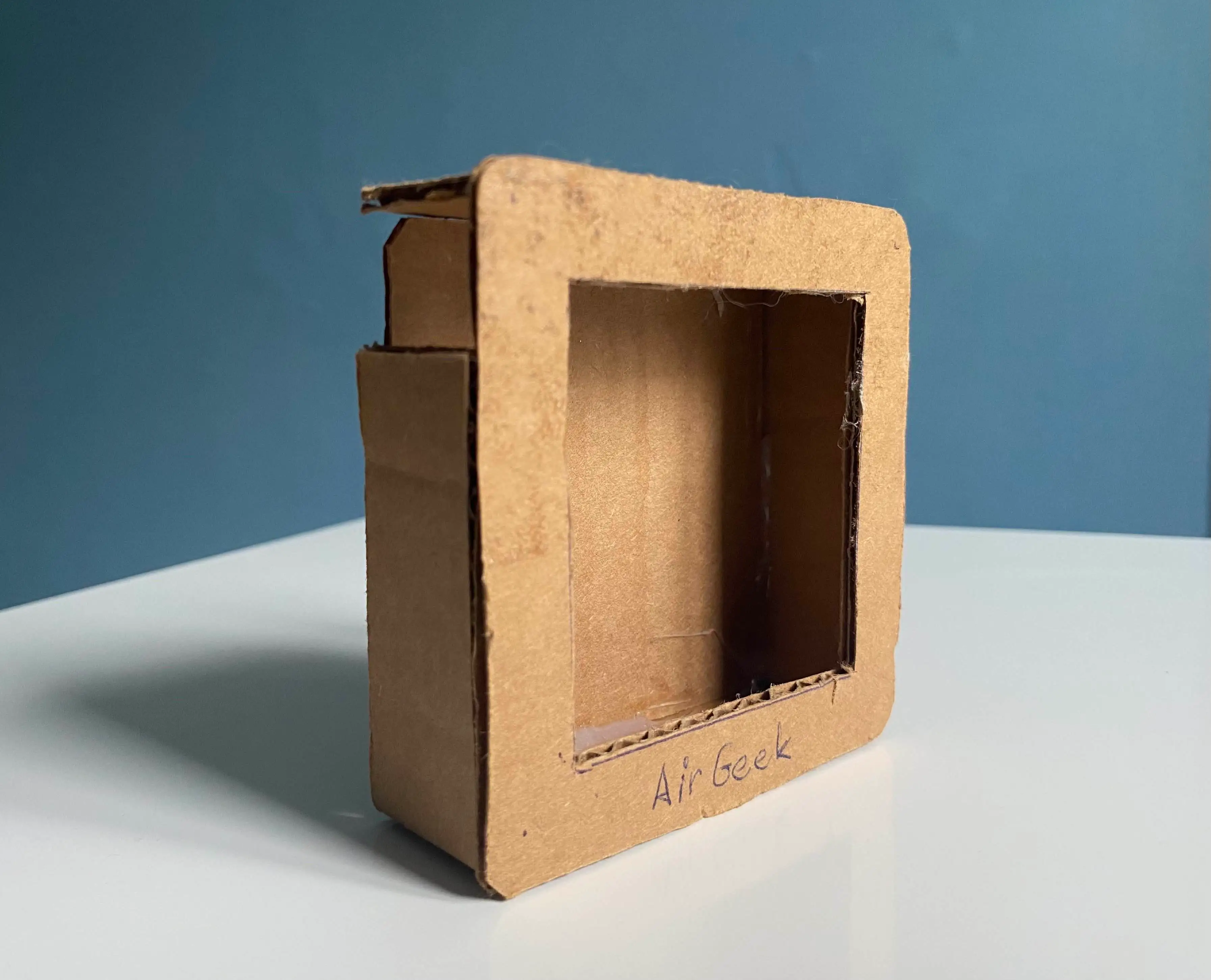
This isn’t entirely true. There actually was a precedent, a CAD model by David. According to him, CAD stands for Cardboard-Aided Design and this is his 2024 masterpiece. And now you know why design became my responsibility!
Humble FreeCAD beginnings
Nowadays, the method of choice for fast prototyping is obviously 3D printing, and I happened to have a brand new Prusa Mk 4s waiting on my desk and ready for action. So this was a given.
The choice of software to do the design work in was a little bit trickier. After some experiments, I decided to use FreeCAD—mostly for the following reasons:
-
It runs natively on Arch Linux. i use arch btw.
-
It is free and open source, giving us the opportunity to share the models with the user community.
-
There are a ton of intro videos and tutorials. Sometimes, it’s even what I would call user friendly.
-
Annoying repetitive tasks can be scripted in Python.
I started with simple objects and boolean functions. If you’re familiar with any CAD software, you probably know how difficult it is to build even simple things this way. But you can strongwill anything into existence, even if it’s a bit painful at first.
I started with a base object and slowly progressed toward the final shape by adding and subtracting other objects, like this:
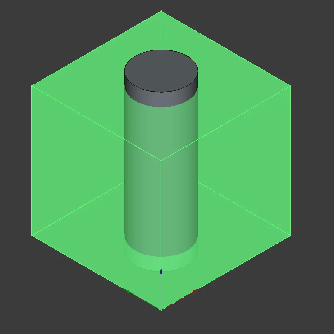
A boolean operation: subtracting a cylinder from a cube to arrive at a cube with a hole in it. Basically drilling.
There are many useful modules which will make your life a lot easier when working this way. For example there’s a module with fasteners (https://wiki.freecad.org/Fasteners_Workbench). That way, you can easily create reliable locking mechanisms or threads for screws:
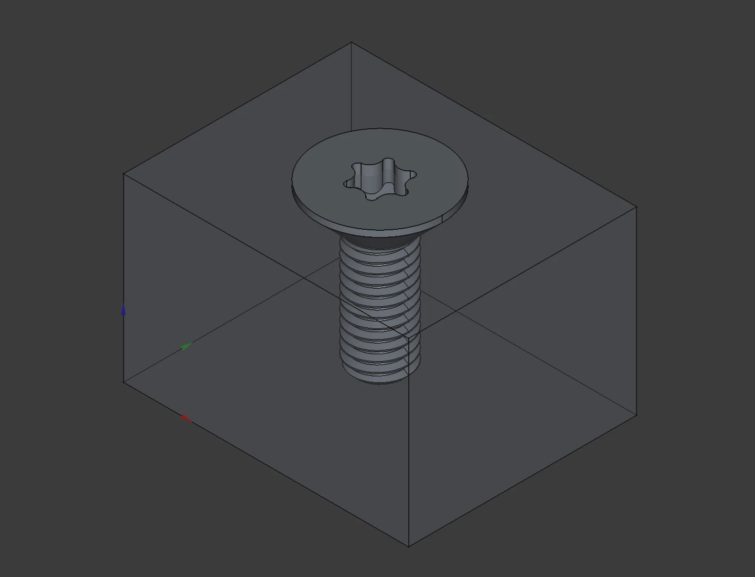
Behold, for this is a screw.
As time went by, I learned to use more advanced tools.
A laundry list of requirements
We started from a prototype PCB, a display, and a set of design requirements and constraints:
-
The environment inside the case needs to be representative of the outside environment. In other words, the case needs to be sufficiently airy.
-
The device is powered by two AA batteries which need to be easily replaceable.
-
The device should be compact with little dead volume inside.
-
There has to be support for some user interface such as buttons.
-
The display needs to be blend seamlessly into the rest of the device and must be easy to read.
-
Durable enough to survive an occasional drop or rough handling.
-
Premium finish on the exterior instead of cheap plastic.
-
And of course, amazing overall look and feel.
Oh, and one more thing: Airgeek A1 & M1 use BMV080—a novel particulate matter sensor made by Bosch Sensortec with no fan. It operates on the principle of laser back-scattering: think a tiny dust radar.
This sensor is one of our key enablers: it’s very accurate, it’s tiny and has no moving parts, and it fits into our power budget. But ease of integration isn’t exactly one of its strengths. It comes with a very strict set of integration requirements and constraints of its own:
-
The laser lens has to be at most 0.2±0.1 mm from the surface of the cover glass. You read that right.
-
The protective glass covering the lens has to have specific parameters, as to not interact with the laser beam with unpredictable ways.
-
There’s a certain keep-out area around the sensor where nothing can be placed, otherwise the laser will collect unrelated backscatter. For a device which is meant to stand of its own, this is a problem.
-
The lens compartment itself needs to be protected against particulate matter contamination, otherwise the readings won’t make any sense.
-
Additionally, the sensor needs to be thermally coupled to a heatsink for reliable continuous operation.
Our first 3D print
With all this in mind, I started designing—and well, it was a wild ride. Judge for yourself:
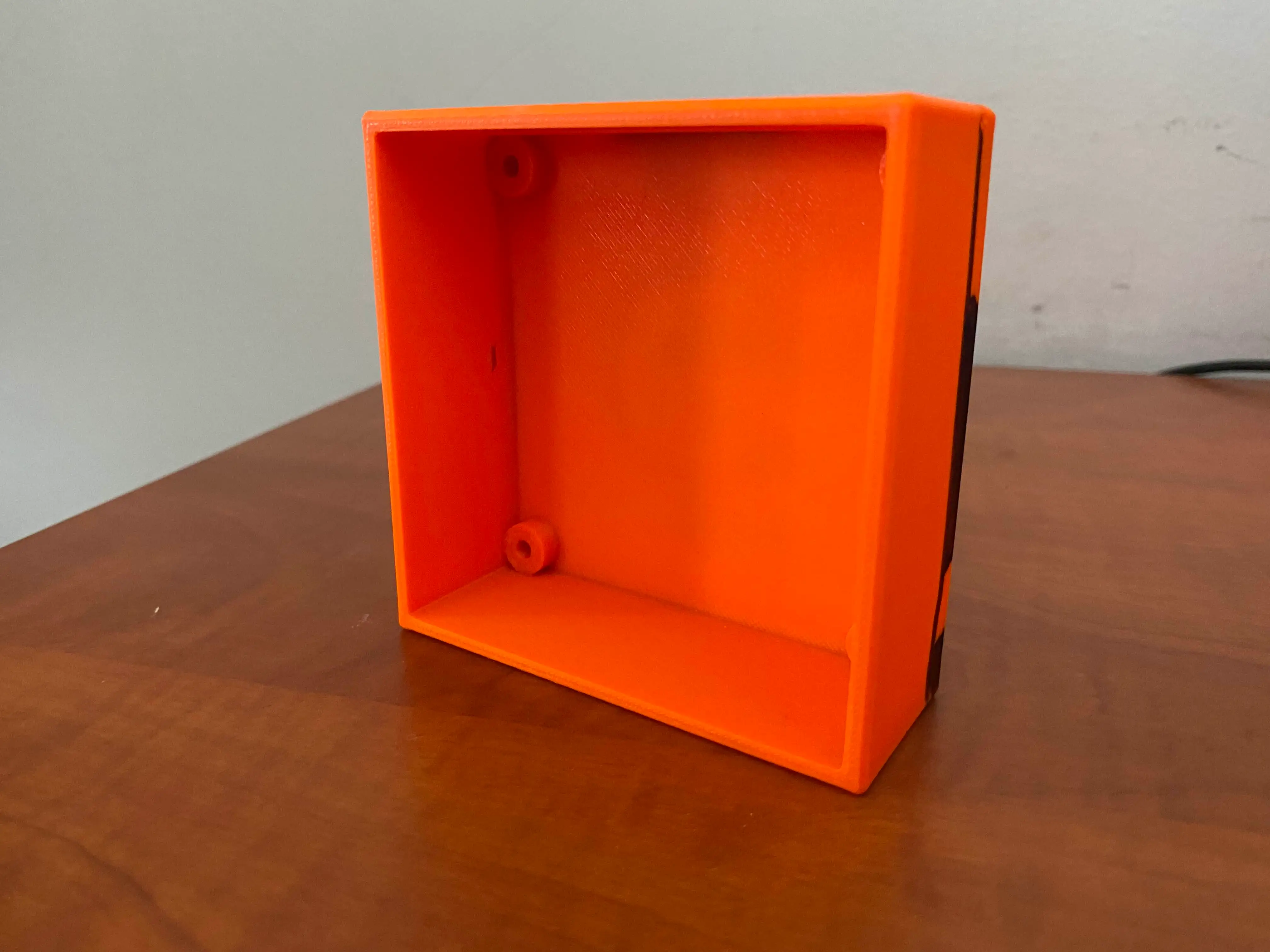
Pro tip: if you make it orange, people will understand it’s just a prototype and won’t beat you if you dare to bring this to a meeting.
I know what you’re thinking. Horrible, right? But for us, it was a proof we can create something. And the difference between having nothing and having at least something is huge. So yeah, I was proud of myself! And you can bet it was durable as hell.
Prototyping was really fast—we were making huge leaps every day. I believe this image speaks for itself:
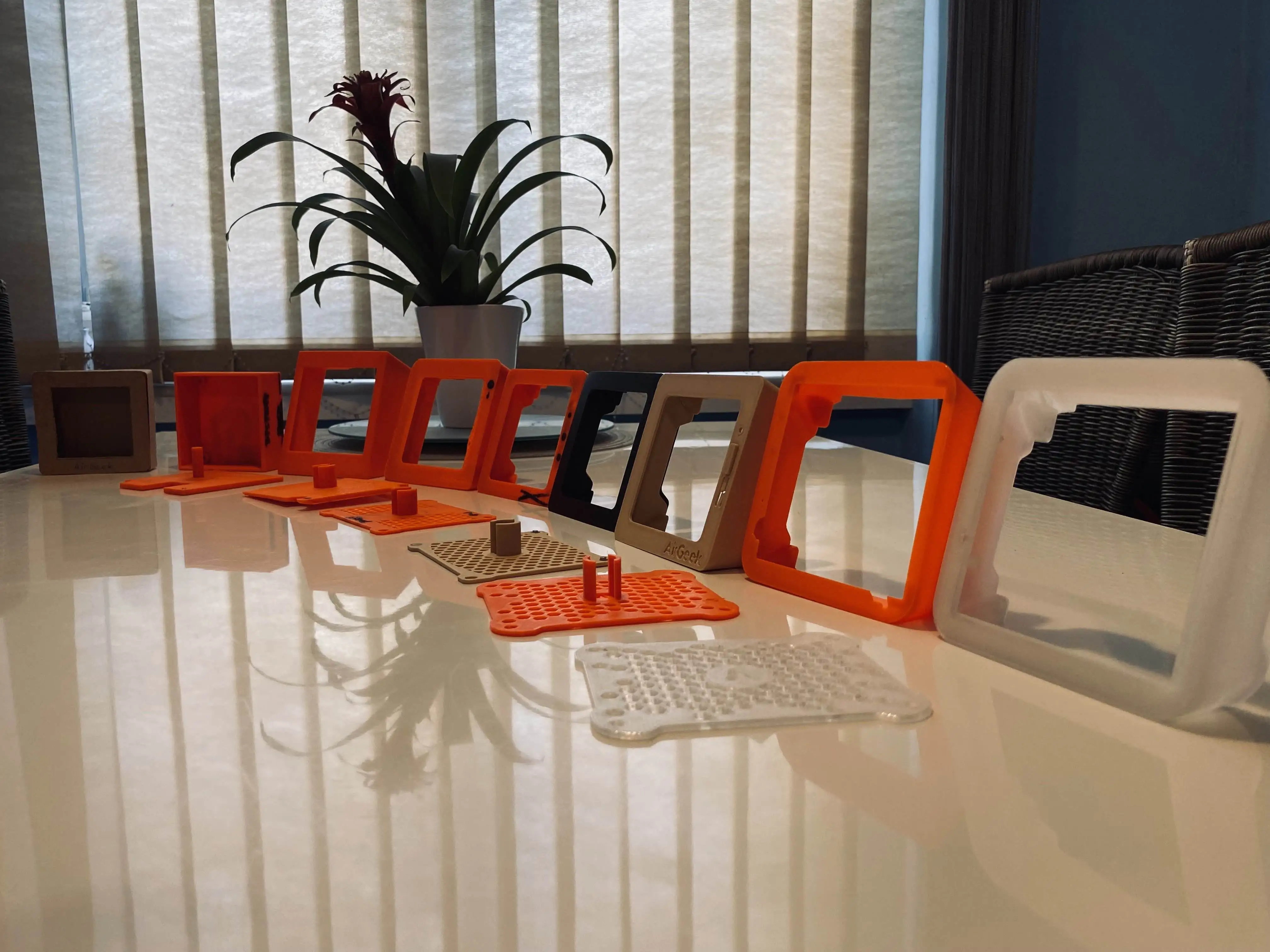
From left to right, this sequence starts with the original “CAD” design and moves towards a fairly complicated model that fits the electronics perfectly.
The methodology was very simple: redesign it, print it, try it, draw all over it, repeat. We’ve created a lot of unique designs which turned out to be dead ends:
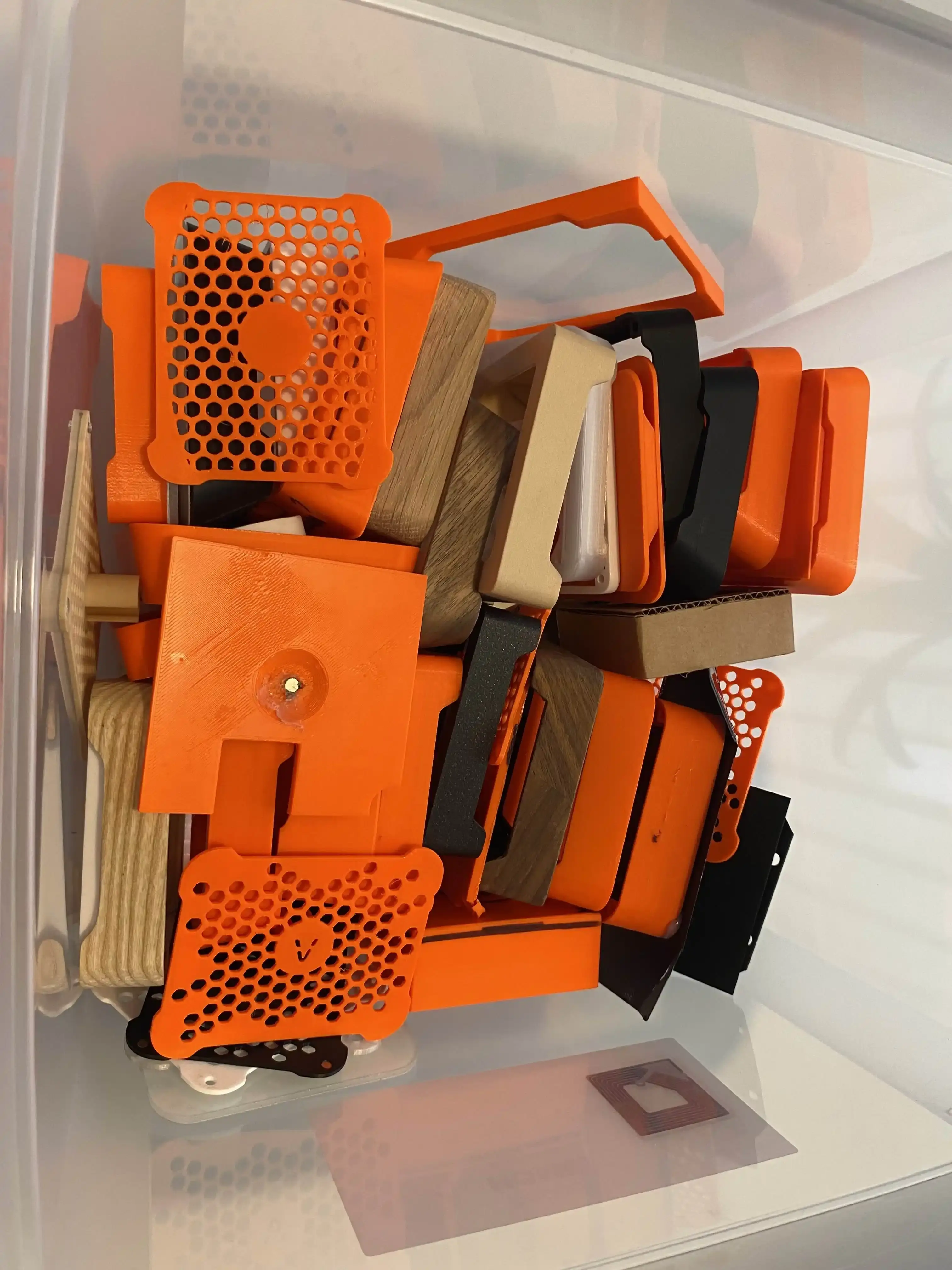
Every single one of those designs eventually earned a nickname. Visible in the picture: Shrek, peninsula, balcony, cobblestone and the ominous Borg cube. Most of the names either reflected how ugly something was or hinted upon the way the BMV was integrated—integrating the sensor right turned out to be quite a challenge.
After a few weeks, we had something that resembled a product you might even put into your home—maybe. But the case was still plastic, and a far cry from the look and feel we aimed for.
We even tried various types of filaments, including one with wood in its structure, but none of them had the right feel. We knew that a case made from actual solid wood would feel amazing, but the manufacturing was way beyond our capabilities. After all, we were only just barely getting started with 3D printing.
So we came up with the idea of using wood veneer on the exterior of the printed case. Wood veneer is a thin layer of real wood laminated over another material—in our case over the PLA “core”. The idea was to get rid of the plastic on the outside, but keep the advantages of the 3D printed core.
This meant that each device was unique and there were limitless color options:
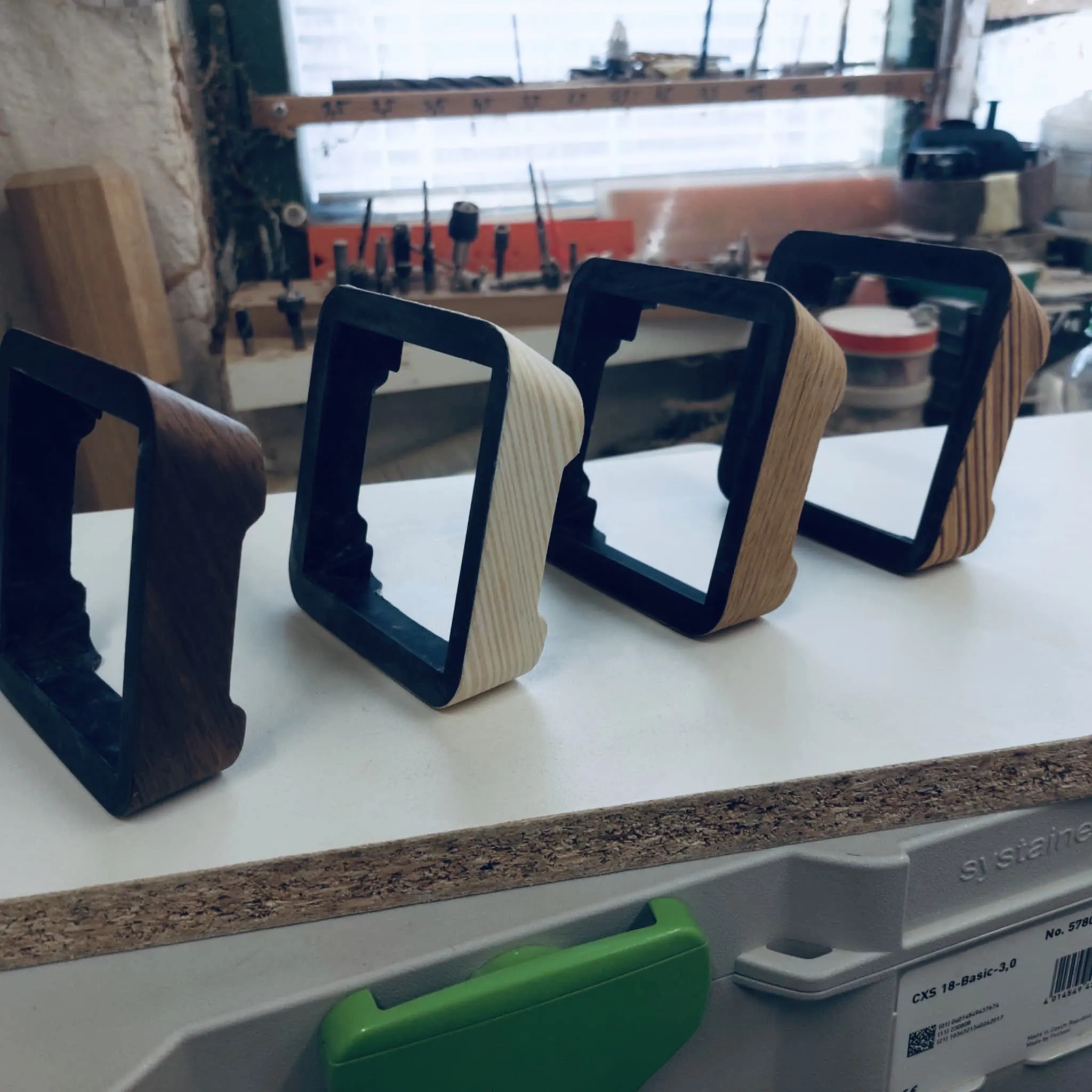
Huge props to Milan Rost, our friend and master craftsman who painstakingly put these prototypes together just in time for embedded world 25.
We decided to use custom-cut Gorilla Glass on the front face, as Gorilla Glass is not only compatible with the particulate matter sensor, but also stylish and scratch-resistant. Combined with the capabilities offered by 3D printing, this allowed us to create a hollow cavity for the PM sensor in the core covered by the glass on one side, and a thermally coupled PCB on the other side.
Unfortunately, the process of laminating the veneer to the core was super difficult due to the complex shape of the device. We wanted to keep only a single “stitch” on the bottom of the case to preserve the perfect look of uninterrupted grain, so we had to use a single wide piece of veneer and waste quite a bit of it. Also, the veneer had to be glued, which led to unintended contamination of other parts of the case. It was a mess.
Detour: Consulting the pros
An important thing to keep in mind is that we’re all originally software and hardware developers, not industrial designers. The device looked “okay”, but we knew it could still be much better. At that point, we decided to consult our work with professionals. We basically told them to go wild and they did. They came up with the following design:
This design is modeled after a house by Gio Ponti. Internally it became affectionately known as “the Borg cube.”
And that didn’t feel quite right, either. So, back to the drawing board.
Keeping it real
The idea of crafting the entire exterior from a single piece of solid wood kept popping up. We knew it was the right way to do it, but the manufacturing just seemed impossibly complicated.
We needed high precision and reasonably fast production—in other words, a CNC mill. But where do you find a CNC mill and a company willing to prototype only a few pieces, not thousands in a batch?
The answer is to find a community workspace. We were incredibly lucky to find Ponk Space. This place is full of machines and amazing people willing to help.
And so, before we knew it, we had our first enclosure made from a solid block of oak:
Kudos to Martin who owns and runs ponk.space, and the amazing team of people around him. We would never be able to get going with CNC milling if we were to learn from scratch.
Switching from printing to CNC milling required some mental gymnastics. As 3D printing is an additive process (you add material to create stuff) and CNC milling is a subtractive process (you remove material to create stuff), at times they feel like complete opposites. What is easy to print can be a hell to mill, and vice-versa.
Now that we created the exterior from solid wood and figured out how to do the necessary finishing steps such as sanding, polishing and oiling, we still had to figure out how to marry it to the hardware inside. We already had these things figured out in the 3D-printed version, and now we had to start from scratch.
CNC in action!
This was when we realized there was one additional design constraint we forgot: easy to repair. For example, if you break the display, you should only need to replace the display, not the wooden frame or the electronics. So glue was out of question.
Best of both worlds
One particular very productive afternoon, we figured out how to have the pie and eat it: by combining 3D printing with CNC milling. We dusted off our 3D-printed core design and modified it to fit into the new wooden frame.
We split the core into two parts:
-
The lower core which holds the Gorilla Glass and houses the LCD panel. The glass and the panel are optically bonded for performance, and the resulting sandwich is then glued to the core. This is the only place where the use of glue was justified. The lower core also holds the PCB in place.
-
The upper core which defines the battery compartment and locks everything together against the wooden frame with four Torx screws. The removable backplate is magnetic and latches onto those four screws.
3D printing tips
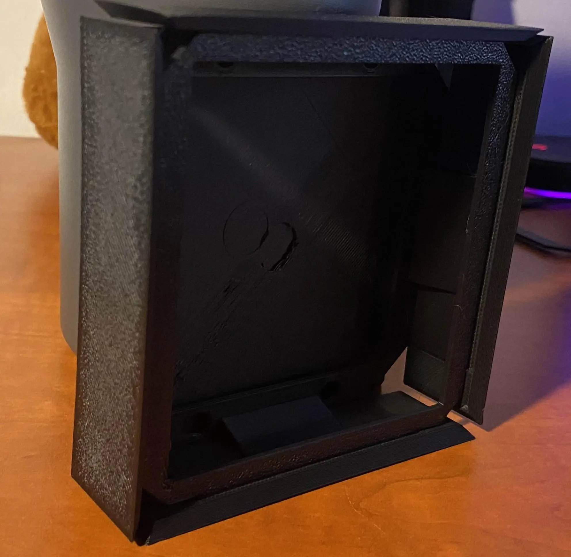
#1 3D prints are way stronger than you think!
To make the device durable, I set the width of all faces to be 4 mm. As you can see in the picture above, this resulted in a truly unbreakable case (and horrible waste of material). For a device like this, you can achieve perfectly adequate strength with less than half that width, and in the end, we used only 1.5 mm thickness and it worked like a charm.
This also applies in the case of infill. Usually, you do not need infill above 25 %, because the internal scaffolding is very strong.
#2 Schwarzkopf solution to the print plate adhesion problem
Certainly one of the worst problems I have encountered while printing was total loss of print plate adhesion for seemingly no reason. This happened for the first time a few days before the Embedded World exhibition in Nürnberg where we hoped to showcase the device for the first time.
As the third general Murphy’s law states: “If there is a worse time for something to go wrong, it will happen then.”
The first few prints of the core were without any problems. But as the print quantity increased, problems emerged. The prints suddenly detached from the print plate. We thought the plate was just greasy, so we cleaned it thoroughly and tried again—no luck.
After a bit of googling, we found a post that suggested the use of IPA (Isopropyl Alcohol) to degrease the plate. Don’t do that!
It worked for a while, but a few days later the print plate lost every adhesion it had. It was really weird because we saw that the filament stuck to the edge of the plate, but not to the actual print area.
We bought a new print plate and the problems were gone for a while, but after a few uses of IPA, we were right where we started. At this point I was getting desperate and tried every advice I found with no success, until a friend advised me to use hairspray on the print plate before print. It worked like a charm.
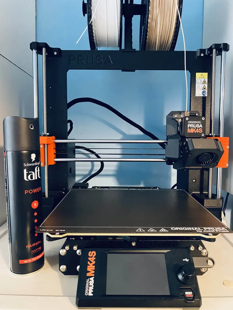
Every DIY hacker needs a 3D printer and a can of Schwarzkopf Taft. Prusa should be selling these, rebranded as official consumables. Orders above $50 get a Taft for free!
My friend claims that with this so-called Schwarzkopf solution, you can even use a thin glass plate on top of a broken print plate and print, but I never tried that myself.
In the end, I would recommend cleaning the print plate only with soap and warm water. And then Schwarzkopf the hell out of it.
#3 Use higher temperature for testing
During development, we needed to create flexible forms for experiments with concrete (yes…) and decided to use TPU to print those. We used Forward AM Ultrafuse TPU 95A Black filament which is sold by Prusa directly.
The manufacturer states that the optimal printing temperature for this filament is between 210–230°C, but that proved to be wrong.
We used 220°C for my first print attempt and right from the get go, the filament was getting stuck in the Nextruder gears. I was afraid to use brute force to get it out. It got easily deformed and pressed into the gears, and after half an hour of futile attempts, I gave up and used pliers and just pulled it out.
Later I figured out that the filament does not get stuck quite so often when I raise the printing temperature above 230°C, we even used 240°C—it worked without trouble.
When using some filament for the first time, it’s a good idea to start on the upper end of the temperature range. That may turn out to be too much for reliable printing, but you don’t run the risk of jamming the feed.
#4 Dark-colored filaments behave differently from light-colored ones
This is a simple problem that most printers figure out pretty fast, but here it goes anyway.
Obviously, every type of filament behaves differently. But even among the same types of filament from the same manufacturer, the black ones tend to have a slightly different optimal printing temperature.
I do not know why that is, but if you keep the temperature within the recommended range, i.e. 250–270°C for Prusament PETG Carbon Fiber Black, you will most likely end up with a deformed part.
#5 Use PETG for veneer laminates
You do not have to use PETG, but use a filament with a high melting temperature—at least 240°C. PETG is very common, so I went with that.
Veneer lamination typically requires hot steam steam (around 180–200°C) to bend it into the desired shape, especially if you have rounder corners as we do. If you use PLA with a melting point of around 210°C, you run the very real risk of melting your entire part. Guess how we know!
Interestingly, heat-treating the core in this was resulted in a much stronger part, presumably because it gave the layers another opportunity to fuse together.
#6 Build in some slack
While prototyping our enclosures, we often needed to make two prints which needed to fit together (the upper and lower core). We figured out very quickly that if you design the parts with precision in micrometers, they won’t fit.
First of all, the printer itself isn’t so accurate. And second, as the parts cool, they deform slightly, introducing errors. How much depends on the type of printer, type of filament used, printing temperatures, ambient temperature and humidity, etc.
Already during the design phase, it’s a good idea to build some slack into your parts. I grew the habit of removing 0.125 mm from each part which usually results in a snug fit that doesn’t get stuck during assembly.
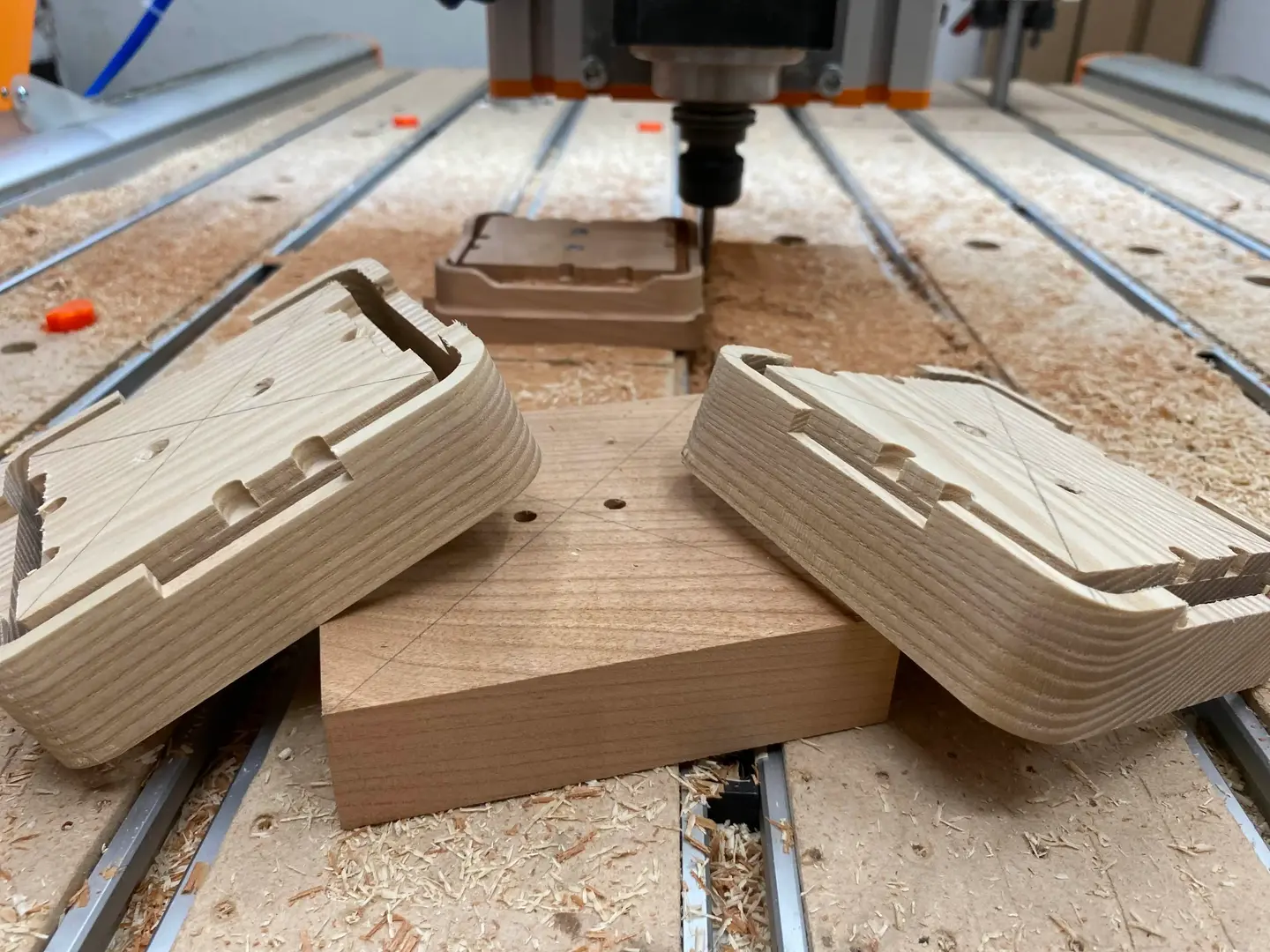
#7 Bonus tip: CNC milling
-
CNC mills go top-to-bottom, so you have to be able to create your model by removing material in that direction.
-
The minimal recommended thickness of your structure is 4–5 mm. Anything less and you risk parts flying across the room when touched by a spindle spinning at 20k RPM during a finishing pass. Guess how I know.
-
Angles that require more than just XY-plane movement will either look bad (like a staircase), or will take way more time to print (smaller steps), or will require manual finishing:
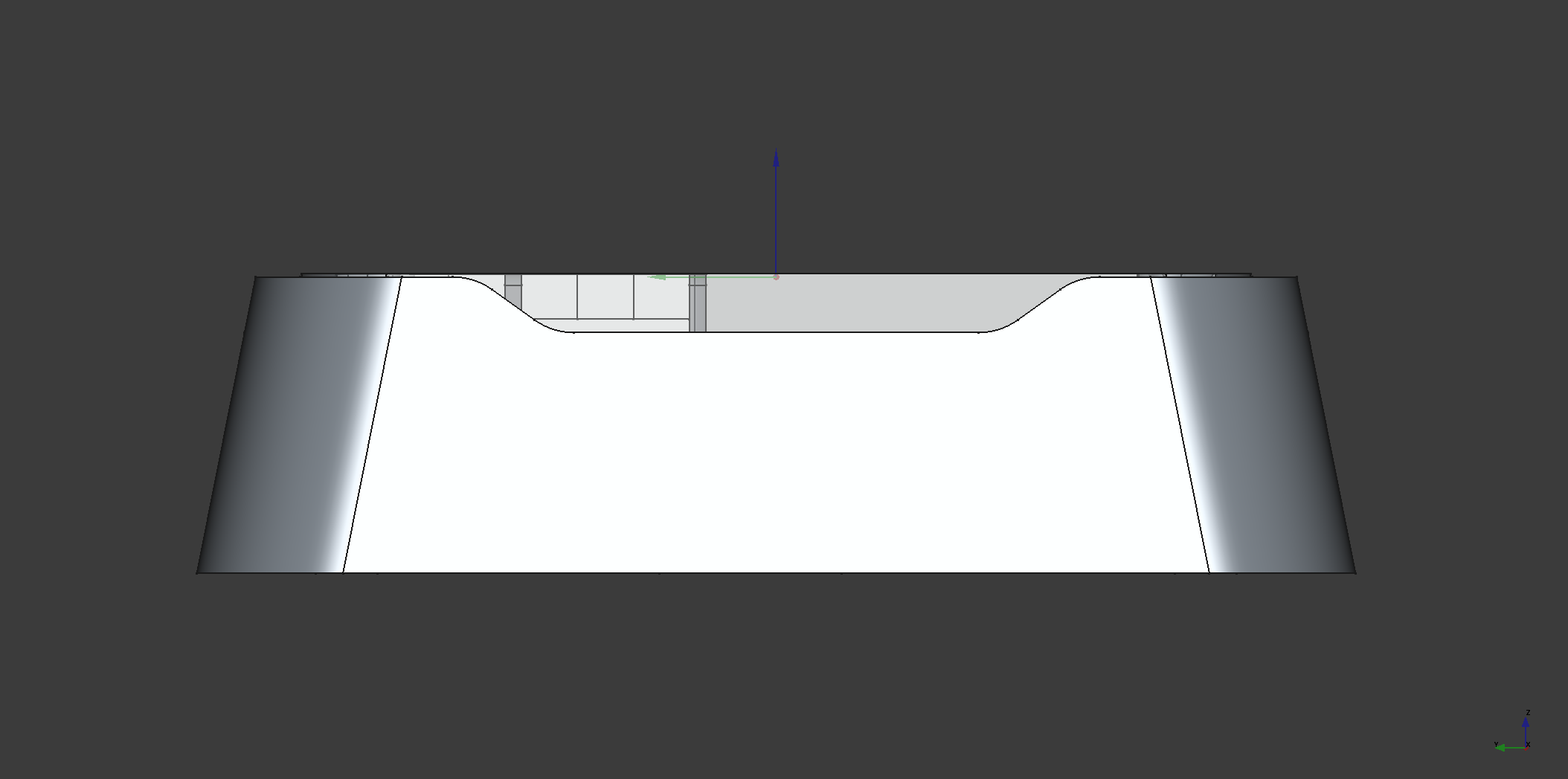
These angles cause trouble, but are a crucial part of the design. They allow free circulation of air throughout the enclosure.
-
For the machine and wood combination we were using, the maximum recommended angle was around 11 degrees.
Closing thoughts
At the beginning, we were quite skeptical when it came to our ability to create something beautiful. But taste in design, like almost everything else, is an acquired skill. In the end, the process of building something physical was extremely rewarding.
With the enclosure done, my next task is to ramp up our production capacity with what we have at hand. Each wooden frame will still get the love it deserves during the finishing process, but the parts which are automated like CNC milling or 3D printing, needs to run much smoother. Right now milling is the bottleneck, so we’ll start with that and keep you posted.